Radio Frequency Directional Power Sensor |
Overview
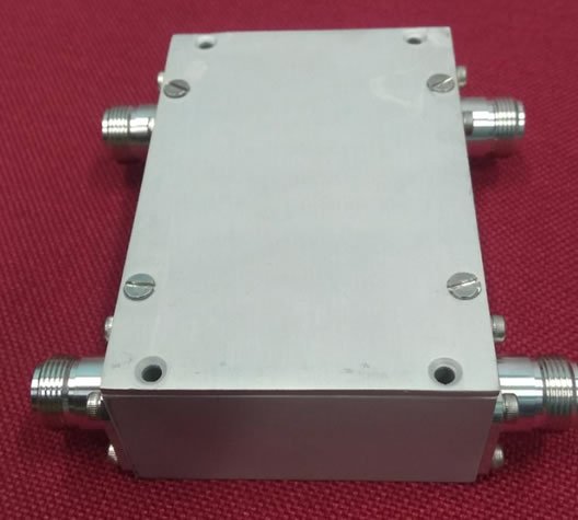
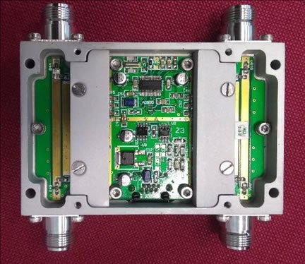
For high power Radio Frequency (RF) systems, power monitoring and sampling, at different junctions is a necessary process for system commissioning, fault debugging and health monitoring. This task is accomplished with the help of directional RF power sensor, mostly imported in India from foreign countries. It acts as a single channel plug-in device in the transmission line of RF systems for providing RF power in forward and reverse directions. A newly designed high power (500 W) directional RF power sensor with dual channels is developed in DAE. It is a thru line coupler and sensor with built-in digital conversion and scaling of data. The converted data is represented in direct milli-dBm unit and is communicated on standard RS422/485 interface. It is compact in size, accurate, cost efficient and indigenous product when compared to imported unit. It does not need any meter to monitor RF power. Optionally it can be interfaced to a normal computer.
Quick View Leaflet
For high power Radio Frequency (RF) systems, power monitoring and sampling, at different junctions is a necessary process for system commissioning, fault debugging and health monitoring. This task is accomplished with the help of directional RF power sensor, mostly imported in India from foreign countries. It acts as a single channel plug-in device in the transmission line of RF systems for providing RF power in forward and reverse directions. A newly designed high power (500 W) directional RF power sensor with dual channels is developed in DAE. It is a thru line coupler and sensor with built-in digital conversion and scaling of data. The converted data is represented in direct milli-dBm unit and is communicated on standard RS422/485 interface. It is compact in size, accurate, cost efficient and indigenous product when compared to imported unit.
ADVANTAGES
The sensor has been developed on the above integrated scheme and offers many advantages, listed below.
- Compact – it is small in size as compared to imported counterparts
- Low Power consumption
- Integrated non-linearity correction
- Distributed computation through RS 485 interface, If required multiple sensors may be daisy chained by using a hub.
Detail Technical Brochure
INTRODUCTION
For high power Radio Frequency (RF) systems, power monitoring and sampling, at different junctions is a necessary process for system commissioning, fault debugging and health monitoring. This task is accomplished with the help of directional RF power sensor. It acts as a single channel plug-in device in the transmission line of RF systems for providing RF power in forward and reverse directions. This document describes a newly designed high power (500 W) directional RF power sensor with dual channels. It is a thru line coupler and sensor with built-in digital conversion and scaling of data. The converted data is represented in direct milli-dBm unit and is communicated on standard RS422/485 interface. It is compact in size, accurate, cost efficient and indigenous product. It does not need any meter to monitor RF power. Optionally it can be interfaced to a normal computer. It has capability of separating RF powers, propagating in two different directions by virtue of novel coaxial to microstrip coupler. This is useful for measurement of forward and reflected power in a variety of RF power generation and antenna systems. It is a thru-line dual channel sensor thus it can be used for measuring RF power while system is working (without terminating) and monitoring line or load condition in various RF systems. For example, application in solid-state high-power amplifier systems can be quoted, where a huge requirement exists for accurate and reliable measurement of forward as well as reflected powers of the amplifier modules.
TYPE AND APPLICATIONS
- Device Type: Two channel through line directional RF power Sensor
- Coupler: Rigid coaxial main line and micro-strip secondary line
- Function: Thru-line RF power measurement
- Application: Specially suited for large channel embedded RF measurement applications
RF PERFORMANCE
- Frequency Range: 300 MHz to 700 MHz
- Power Handling/Withstanding: 1 kW max.
- Calibration: Narrow band calibration on single frequency of use
- Measurement Range: 5 W to 500 W CW and 20 W to 2 kW Pulsed
- Typical Relative Accuracy: ±0.2 dB maximum in full range and ±0.1 dB RMS error
- Typical Directivity: 20 dB min (after calibration)
INTERFACE SPECIFICATIONS
| Interface Connections | RJ45 socket (8P8C) |
| Communication | RS485 full/half duplex |
| Serial Settings | 28800 baud rate, even parity, 8 bit data, single stop bit |
| Electrical Power Requirement | 9 V to 24 V DC (≤100 mA) via above interface connector |
| Daisy Chaining | If required multiple sensors may be daisy chained by using a hub. |
PHYSICAL SPECIFICATIONS
- RF Connectors: N-type connectors (receptacle) for all RF ports
- Size with RF connectors: 110 mm x 108 mm x 35 mm (L x W x H)
- Size excluding connectors: 70 mm x 108 mm x 35 mm (L x W x H)
- Gross Weight: ≤ 800 gm
- Enclosure: Passivated Aluminum enclosure
TYPICAL END USERS
It is a thru-line dual channel sensor thus it can be used for measuring RF power while system is working (without terminating) and monitoring line or load condition in various RF systems used for strategic applications. For example, application in solid-state high-power amplifier systems can be quoted, where a huge requirement exists for accurate and reliable measurement of forward as well as reflected powers of the amplifier modules.
MANPOWER
| Sr. No. | Designation | Nos. |
| 1 | Technical officer (B Tech in Electronics Engg) | 1 |
| 2 | Technical Supervisor (Diploma in Electrical/Electronic Engg.) | 1 |
| 3 | Operators/Technician(ITI) | 1 |


