Rigid Coaxial Transitions |
Overview
High power rigid coaxial line RF components like Power Combiners, Directional Couplers, RF Circulator and Rigid Coaxial line sections are integral parts of any High-power RF system. To characterize/qualify these high-power RF components, their accurate low power RF measurements are required. These RF measurements are evaluated with the help of Vector Network Analyzer (VNA). For these RF measurements to be precise, accurate Coaxial Transitions are required depending on coaxial line size of RF component. A family comprising of 3-types of Coaxial Transitions (for 1 5/8 inch, 3 1/8 inch and 6 1 /8-inch rigid coaxial lines) have been designed and developed with operating frequency range from 300 MHz to 700 MHz. Depending upon application, any type of transition may be useful.
MAJOR ADVANTAGES
The developed Rigid Coaxial Transitions, offer several advantages:
- Low thru line VSWR (≤ 1.1)
- Low insertion loss: ≤ 0.05 dB
- Wide operating frequency range (300 MHz to 700 MHz)
- Integration – Three choice of EIA flanges -1 5/8 inch or 3 1/8 inch or 6 1/8-inch, easy to integrate in High power RF Systems.
- Compact form factor –light weight and compact size due to conical design
Quick View Leaflet
Rigid Coaxial Transitions are mandatorily required for low power RF characterization of various high-power RF components, to be utilized in High power RF systems for various VHF and UHF RF systems. High power rigid coaxial line RF components like Power Combiners, Directional Couplers, RF Circulator and Rigid Coaxial line sections are integral parts of any High-power RF system. To characterize/qualify these high-power RF components, their accurate low power RF measurements are required. These RF measurements are evaluated the help of Vector Network Analyzer (VNA). For these RF measurements to be precise, accurate Coaxial Transitions are required depending on coaxial line size of RF component. A family comprising of 3-types of Coaxial Transitions (for 1 5/8 inch, 3 1/8 inch and 6 1 /8 inch rigid coaxial lines) have been designed and developed with operating frequency range from 300 MHz to 700 MHz. Depending upon application, any type of transition may be useful. Various types of Rigid coaxial line RF components of Solid-State RF amplifier systems, deployed in Synchrotron Radiation Source (SRS) Indus-2 as well as for Proton accelerator program of RRCAT, have been qualified/characterized with these N-type Coaxial transitions.
SPECIFICATIONS OF RIGID COAXIAL TRANSITIONS
Type and Applications
- Device Type: Passive N-type to Coaxial Transitions
- RF Interface/port type: N female (50 Ω) per IEC 61169-16 N type on one side and
- EIA 1-5/8 inch or 3-1/8 inch or 6-1/8 inch; all (50 Ω) as per IEC 60339-2 on other side
- Application: As RF port adapter/transition from rigid EIA to N type or vice-versa.
RF Parameters
- Frequency Range: 300 MHz to 700 MHz
- RF Power rating: 1 kW (CW) and 2 kW (pulse)
- Input and Output VSWR: ≤ 1.1
- Insertion Loss: ≤ 0.05 dB
Detail Technical Brochure
Rigid Coaxial Transitions are indispensable measurement components that provide a convenient and accurate means of characterization and qualification of high power rigid coaxial line RF components. A typical high-power RF system consist of RF Power amplifier system, High Power combiners, RF Circulators, Rigid Coaxial line sections and finally some RF Termination (that may be a RF resonator/RF cavity in case particle accelerators). Before integration of all above mentioned RF components, to form a reliable high-power RF system, low power characterization of these components with help of Vector Network Analyzer (VNA) is a necessary pre-requisite. With the help of N-Type Coaxial Transitions, rigid coaxial line interface of these RF components can be transformed to N-type connector which could be readily interfaced with VNA for RF measurements. These rigid coaxial transitions also play a crucial role in final output power calibration of RF power amplifier system and troubleshooting at multiple interfaces of high-power RF system. Mainly three types of transitions are popular for high power RF systems. These are classified based on end (rigid line) EIA flange viz. 1-5/8”, 3-1/8” and 6-1/8”. These N-type transitions are mostly procured from outside the country and will be required for ongoing as well as forth coming DAE projects.
Traditionally, stepped impedance matching based designs are utilized for realization of N-type coaxial transitions. But these are narrowband designs as they suffer from intrinsic lower bandwidth of stepped junction which also results in longer structure length, resulting in bulky, costly and difficult to fabricate structures. Continuous taper impedance matching technique has been adopted for the design of here mentioned N-type Rigid Coaxial Transitions. Length of this continuous taper has been optimized for minimum structure length and best case return loss and bandwidth. A family of three types of coaxial transitions N-type to EIA 1 5/8 inch, 3 1/8 inch and 6 1/8 inch flanged rigid coaxial line interfaces have been designed and developed for low power RF measurements of rigid coaxial line RF components of RF power rating up to 70 kW. Return loss better than 30 dB and operational bandwidth of 300 MHz to 700 MHz has been achieved for all three above mentioned N-type Rigid Coaxial Transition structures. Insertion loss for these N-type coaxial Transitions is also measured by adjoining two nos. of N-type Rigid Coaxial Transition assemblies back to back. Insertion loss less than 0.08 dB was measured for both these assemblies. High return loss and low insertion loss along with wider bandwidth are the main characteristics of Rigid Coaxial Transitions that are inevitable for accurate RF measurements for high power RF components. The processes for synthesis, characterization and efficacy evaluation will be transferred along with the technical data generated in the laboratory.
SPECIFICATIONS FOR RIGID COAXIAL TRANSITIONS
| Sr. No. | Specification | Value |
| 1 | Type and Applications | RF Interface/port type: N female (50 Ω) per IEC 61169-16 N type on one side and EIA 1-5/8 inch or 3-1/8 inch or 6-1/8 inch; all (50 Ω) as per IEC 60339-2 on other side Application: As RF port adapter/transition from rigid EIA to N type or vice-versa. |
| 2 | RF Parameters | Frequency Range: 300 MHz to 700 MHz RF Power rating: 1 kW (CW) and 2 kW (pulse) Input and Output VSWR: ≤ 1.1 Insertion Loss: ≤ 0.05 dB |
| 3 | Mechanical characteristics |
|
TYPICAL END USERS
It is a thru-line dual channel sensor thus it can be used for measuring RF power while system is working (without terminating) and monitoring line or load condition in various RF systems used for strategic applications. For example, application in solid-state high-power amplifier systems can be quoted, where a huge requirement exists for accurate and reliable measurement of forward as well as reflected powers of the amplifier modules. It is also required for cellular base stations, military radar communications, global positioning systems.
FACILITIES REQUIRED FOR COMMERCIAL PRODUCTION
- Necessarily Required Facilities
- Scattering parameter measurement equipment
- RF Load, Cables and other RF accessories
- Optional Facilities (may be outsourced /shared)
Mechanical Fabrication Facility for Enclosure:- CNC machining (VMC or equivalent) for milling, turning etc.
- Chemical cleaning setup
- Tri-chromate passivation setup
- Component Assembly and Testing
- Final assembly setup
MANPOWER
| Sr. No. | Designation | Nos. |
| 1 | Technical Supervisor (Diploma in Electrical/Mechanical Engg.) | 1 |
| 2 | Operators/Technician(ITI, Mechanical)) | 1 |

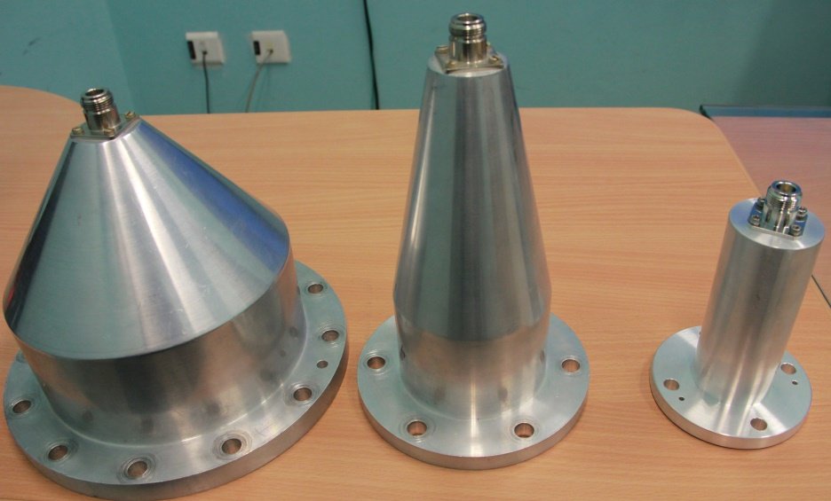
Rigid Coaxial Transitions - 6 ⅛ inch, 3 ⅛ inch and 1 ⅝ inch to N-type (Left to Right)

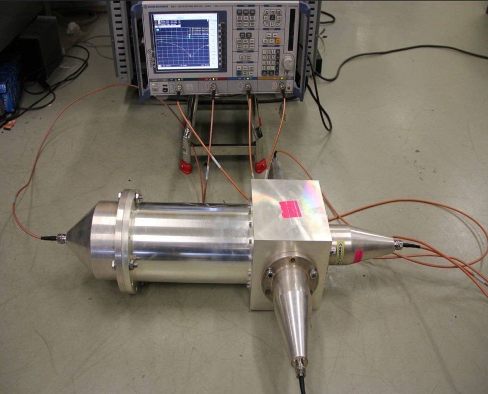
Use of 6 ⅛ inch and 3 ⅛ inch, coaxial to N-type transitions in RF Measurements of 60 kW 3-Way Power Combiner
