Laser Additive Manufacturing System using Powder Bed Fusion System (LAM-PBF) |
Quick View Leaflet
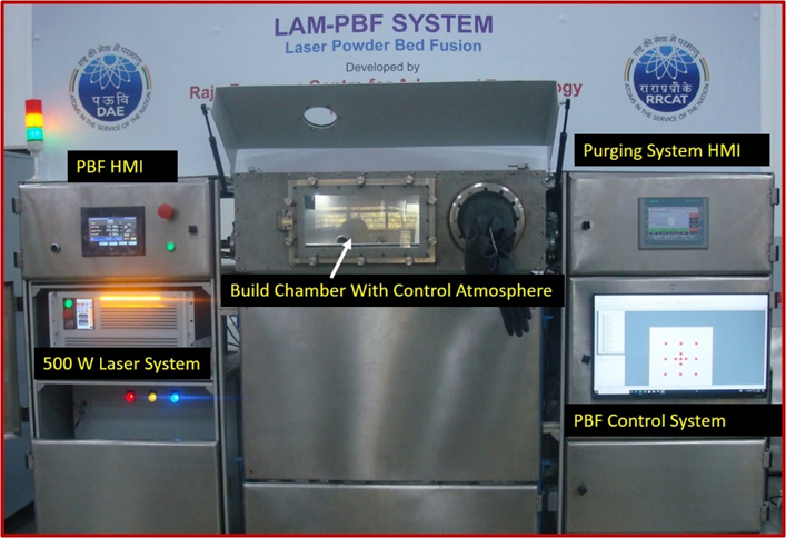
The LAM-PBF system is designed to manufacture 3D metallic components using pre-placed powder bed fusion technology. This process involves creating a thin layer of metal powder on the build plate, followed by laser consolidation in a controlled atmosphere of Argon or N2 to fabricate 3D engineering components. The system integrates various components, including the powder bed fusion module, controlled atmosphere chamber, Human Machine Interface (HMI), Galvo-Scanning system, PBF control unit, laser systems, and computer system. The technology is now available for translation through incubation/ co-development. The newly developed LAM-PBF system is versatile, offering applications in prototyping, product development, manufacturing complex parts, and producing low volumes of various metallic engineering components. It finds utility across a spectrum of industries, including nuclear, aerospace, automotive, medical, and research and development (R&D).
Detail Technical Brochure
Detailed Technical Brochure

Laser Additive Manufacturing (LAM) is a cutting-edge method for manufacturing parts directly from 3D CAD models using a layer-by-layer material build-up approach. Among the latest and most advanced additive manufacturing technologies is Laser Powder Bed Fusion (LAM-PBF), where laser energy selectively fuses regions of a powder bed to shape engineering components in a layer-by-layer fashion. This tool-less manufacturing method can produce fully dense metallic parts in a short time with high precision.
1. Working Principle
The LAM-PBF process utilizes laser energy to selectively melt fine powder particles of the built material to form a solid part. To fabricate a complete 3D part, software decomposes a 3D solid model into a number of 2D slices/layers as per the defined layer thickness. Each of these layers becomes a raster pattern for the laser energy source. After 2D layering, the 3D solid model is built up into a 3D solid part in three steps: first, a powder levelling unit lays down a thin layer of powder on the build plate; second, the laser selectively melts the powder portions of the built surface, creating a 2D slice of the 3D part; third, the build plate is lowered, and the powder hopper is raised to allow for a new layer of material to be deposited. This process is repeated until all of the 2D slices have been stacked on top of each other to create the 3D part.
2. Product Technical Specification
| S. No. | Description | Value |
| a. | Laser | 500 W Fibre Laser |
| b. | Laser Wavelength | 1070 – 1080 nm |
| c. | Working volume | 300 mm x 300 mm x 300 mm (customizable) |
| d. | Environment | Control Atmosphere |
| e. | Power requirement | 3 Phase (415 V AC) with neutral and ground |
| f. | Cooling requirement | Air-cooled |
3. Typical End Applications:
The distinct features of LPBF, such as freedom of part design, part complexity, lightweighting, part consolidation, and design for function, are garnering particular interest in metal additive manufacturing for nuclear, aerospace, oil & gas, marine, and automobile applications.
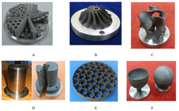
The developed LPBF machine will be capable of processing materials such as austenite steel, Inconel, aluminum, copper, titanium, and their alloys. Various thin-walled, solid, and complex 3D geometries are fabricated to demonstrate the capability of the developed LPBF machine, as detailed below:
 Fig.: Typical geometry fabricated by LPBF System (A) Complex Test Geometry, (B) Compressor Blade, (C ) Gyroid Shape (D) Conformal cooling Channel part (E) Spacer for Fuel bundle and (F) Semi and Full printed Oxygen Bottles.
4. Facilities Required for Commercial Production
a. Floor Space (at least 100 sq m) required for integration and testing
b. Drilling & Fitting facility with general metrology instruments.
c. Electrical test and measurement equipment such as Multimeters, Clamp on Meters, Oscilloscope, Megger, General Kit etc.
d. Utilities like compressed air, cooling water and electrical power.
5. Manpower Requirement
Two graduate engineers (Mechanical and Electronics) having at least two years’ experience in working with machine automation/ robotics/ machine tool development, three ITI trained technicians (One electronics and two fitters) are sufficient to start production.
