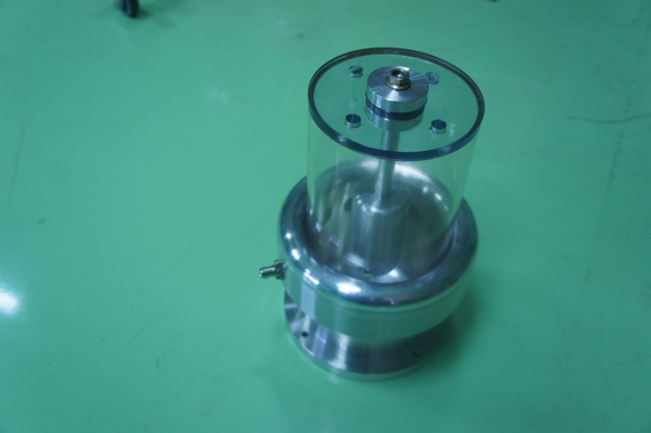
High Voltage Pulse Measurement Device (HVPMD) |
Overview
The HVPMD offers:
- Capacitive in nature so nearly loss-less
- High input impedance, low leakage current
- Minimal power dissipation, compared to resistive dividers
- Adjustable voltage division ratio
- Excellent frequency response
- Low voltage droop
- Provides actual pulse shape
Optimized for:
- Pulse amplitudes up to 250 kV and tested upto 125 kV
- Pulse widths in the microsecond range (0.1 μs-100 μs)
- Rise/fall times of a few tenths of microseconds (0.1 μs)
Ideal for high-voltage pulsed power systems requiring:
- Non-resistive voltage division
- Accurate pulse shape monitoring
Applications:
- Pulsed high voltage measurement and monitoring
- High voltage klystron pulse modulators
Quick View Leaflet
HVPMD is widely used for voltage measurement in pulsed power systems such as particle accelerators, pulse high-voltage generators, where accurate and fast response is desired. The HVPMD offers a high input impedance, low leakage current, low power loss, and excellent frequency response so it enables precise, fast, and safe voltage measurements. Compared to resistive dividers, it offers superior transient response and less heating. It requires a careful design and fabrication. The HVPMD is optimized for hundreds of kilo-volts pulses with micro-second pulse width and few tenths of seconds of rise-fall time.
A High voltage probe consists of two capacitors connected in series, used to divide a high voltage input into a smaller, measurable voltage output. The division is based on the following relationship of voltage and capacitances:
Vout = Vin C1/[C1+C2]
Where, Vin is HV input, Vout is divided low voltage output across C2 , and C1 and C2 are series capacitances.
Detail Technical Brochure
INTRODUCTION
This HVPMD is designed for pulsed high-voltage applications up to 125 kV. It features a robust design with a top-mounted high-voltage terminal, a BNC output at the ground potential and compatible with RG-58 coaxial cable for direct connection to an oscilloscope. The voltage division ratio is configurable during manufacturing to suit specific measurement needs.
Technical specifications
|
Parameter |
Value |
|
Maximum pulsed voltage in oil |
125 kV |
|
Rise time |
< 0.1 μs |
|
Voltage division ratio (oil) |
1:15000 (factory adjustable from 1:10000 to 1:20000 |
|
Droop |
0.02 % per μs |
|
Input capacitance (in air) |
10 pF ± 10% |
|
-3 dB bandwidth |
10 kHz to 3 MHz |
|
Termination |
1 MΩ |
|
Input Connector |
M10 Stud Terminal (Lug Connection) |
|
Output Connector |
BNC (custom options available) |
|
Cable Length effect on vol. div. ratio |
Each 1 m. of RG-58 cable increases the voltage division ratio by 333. |
|
Type |
Oil-immersed, oil with IS-335 and εr = 2.3 |
|
Mounting |
Vertical ( holes provided on base plate) |
|
Height |
250 mm ± 5% |
|
Base Diameter |
182 mm ± 2% |
INFRASTRUCTURE
- Mechanical fabrication facilities preferably a CNC machine, outsourcing may be acceptable
- Electronics PCB assembly facility
- Test instruments like function generator, oscilloscope, multimeter, Meggar etc. for preliminary low voltage testing
- High voltage pulse testing facility, outsourcing may be acceptable.
SPACE
- Floor area ≥ 250 square feet
MANPOWER
One CNC operator, one electronics technician, and one electronics engineer are sufficient to start production.